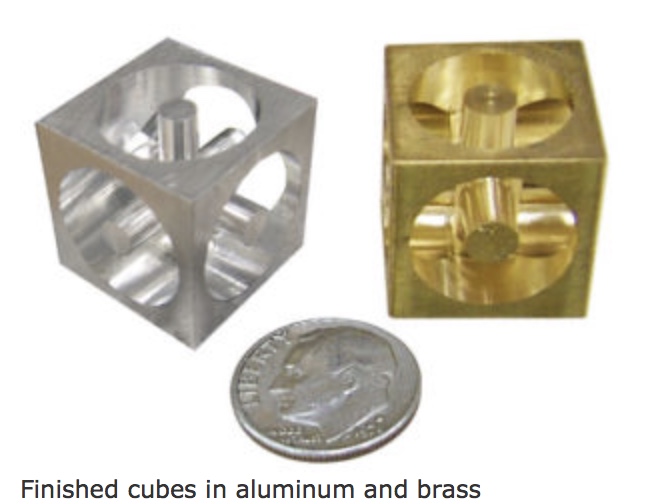
Sherline sells a cube puzzle for $80. I decided to make one from the picture shown below. The plan is to drill four through holes on three sides of a 3/4" cube and then mill out the remainder. The trick will be maintaining rigidity for the last few milling passes.
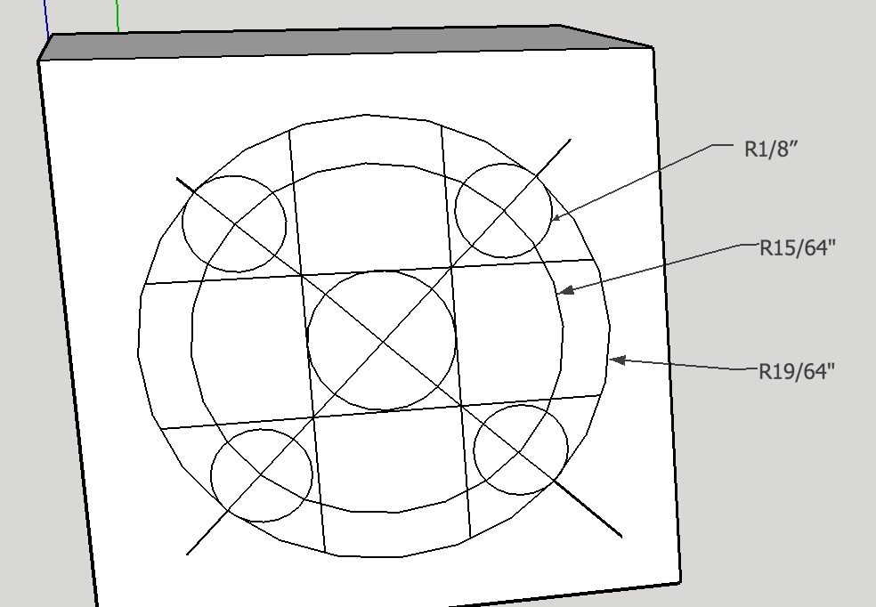
A few measurements taken from an expanded view of the web photo led me to the following measurements. The diameter of the columns is 3/16". The diameter of the circular opening in each side is 19/32". Estimation with graph paper led me to guess that a 1/8" drill would be appropriate for producing four holes around each shaft. This should give 1/8" + 1/8" + 3/16" = 7/16" vs 19/32" or about 3/16" total to be removed by milling from the inside and outside edges.
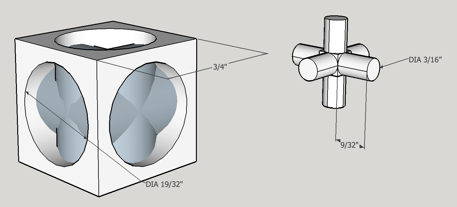
Have no idea how to get the cube to be hollow. Consequently, the "jack" could not be moved into the interior of the cube. The drilling plan is shown separately below. The holes drilled should not be right on the 19/32" circle, allowing some room for cleanup milling.
A 7/8" length of 1" square aluminum stock was cut off with a hacksaw. This was reduced to a 0.750" cube in the 4-jaw chuck on the lathe. Soft jaws were used to minimize marking of the finished surfaces. The rotary table was centered on the milling table using the headstock center from the lathe and an edge finder mounted in the spindle. The cube was centered in the 4-jaw chuck while still on the lathe. The 4-jaw chuck was then transferred to the rotary table.
It was necessary to recenter the cube in the chuck after putting an aluminum spacer below the cube.
The table was offset 15/64" and rotated so as to align the spindle on a line from corner to corner. The first hole was center drilled and then carefully drilled through with a 1/8" drill. The table was turned 90° and the drilling operation was repeated. After two more repetitions the chuck was returned to the lathe and a new face was exposed and centered. The next set of holes was drilled. One more repetition completed the drilling.
The drilled cube still in the chuck was then milled. A 1/8" end mill was lowered about 0.025" into one of the holes. The table was then rotated counter clockwise. The end mill was lowered about 0.025" and the milling was repeated until a final depth was reached ((3/4" - 3/16") / 2) = 9/32" or 0.281". This produced the outer edge of the cutout. The table was then moved closer to center and milling repeated until the remaining rod diameter was 3/16". Climb milling was used to clean both the outside and inside cuts.
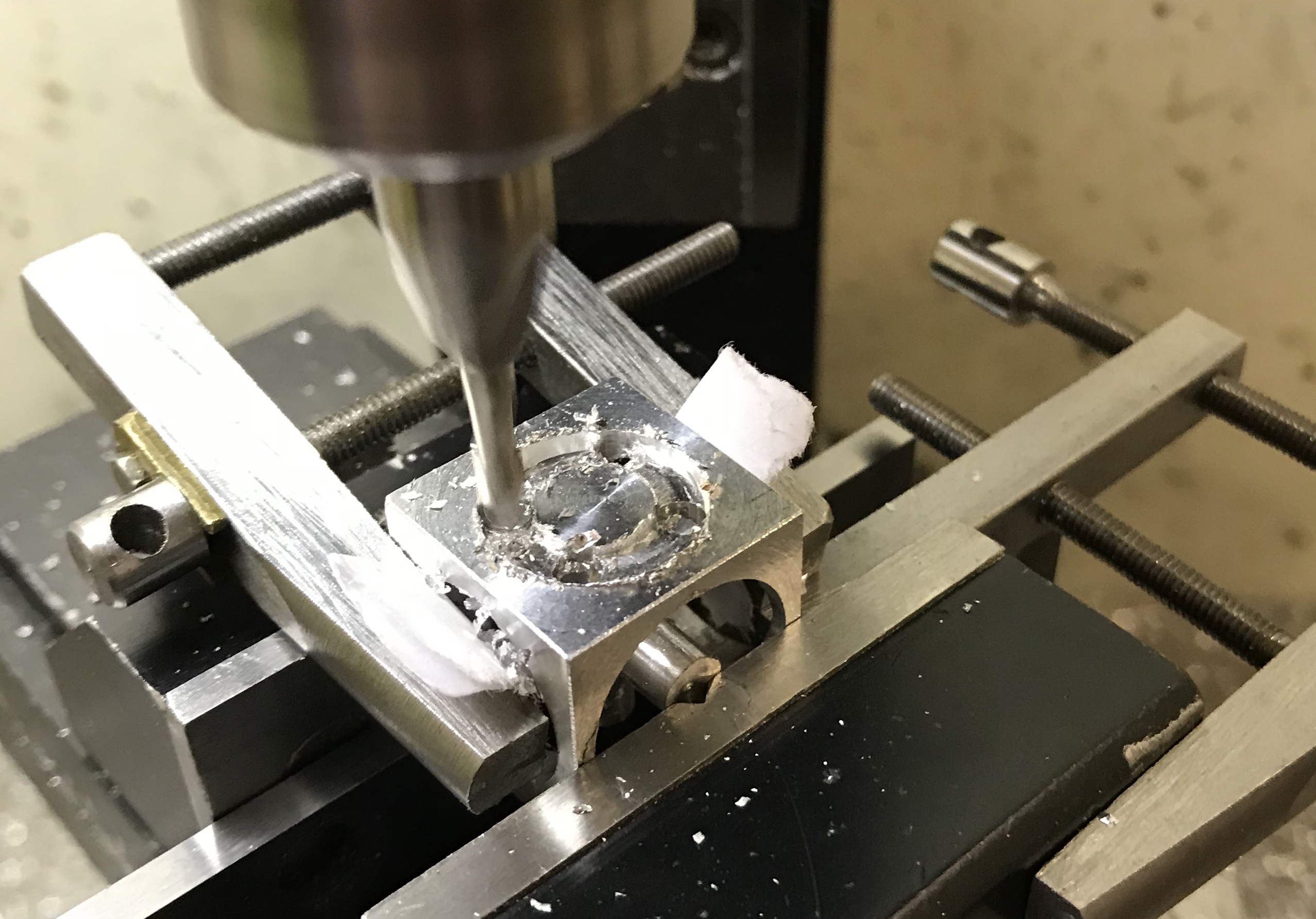
The cube was turned in the chuck and re-centered on the lathe. The above process was then repeated on a new face. It became apparent at this point that the chuck would no longer have the holding power for further face milling. The milled faces have only a thin strip of metal for gripping and the rods in the center are not held at all. Consequently, a decision was made to switch from the 4-jaw chuck to the milling vise. The question then became how best to center the cube in the vise on the rotary table. The cube was not centered in the lathe chuck when the sides were faced, so the 'center' spots were not on center. A piece of 3/4" hex brass was used as a surrogate. A hole in the center of the 3/4" hex was aligned with an edge finder in the spindle. The hex was swapped for the cube and the point of the edge finder was centered on the cube with the use of a ruler. A small machinist's clamp was used as a stop.
The 1/8" end mill was placed in the end mill holder and the table was moved in the x-direction until the end mill was aligned with a drilled hole in the cube. The spindle was lowered 0.025" and the table was turned clockwise. The end mill was lowered in increments of 0.025" and milling the circle was repeated until the end mill touched the spoke from a previous cutting. The table was then moved back toward center again in the x-direction by 0.020" and the circle was cut reducing the diameter of the spoke. This was repeated until the spoke was 3/16" in diameter. A quick climb milling pass in the opposite direction served to clean up the surface of the third spoke. This was successfully repeated on the final three sides. Paper was used in the vise on the last two sides to make sure the central spokes were tightly held in the vise.
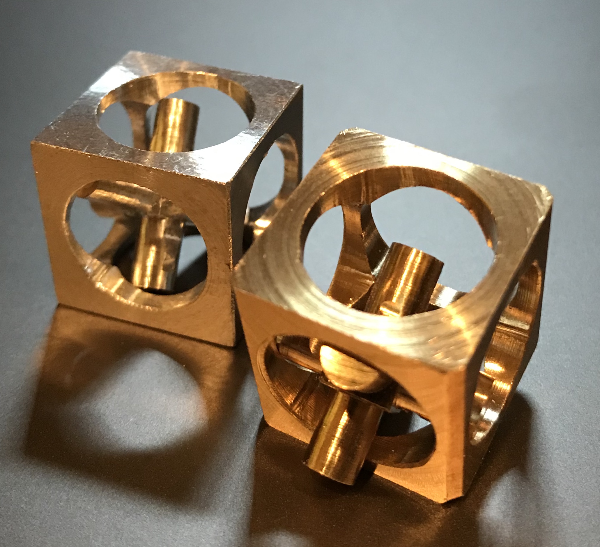
The prototype aluminum "Jack in a box" was completed. One of the holes was slightly larger than the others (the first to be cut) and the "jack" could be removed via this hole defeating the purpose of the construction. Consequently, a new "Jack in a box" will be made from brass using the learning from the prototype.
The only available material was a brass 1" round bar. A 13/16" length was sawn off with a hacksaw and both ends were faced in the lathe. The brass stock was then placed in the mill vise and all four sides were reduced by 0.125" with the two insert end mill in 0.010" passes. This square stock was returned to the lathe and the length reduced to 0.750". This also left a nice center spot on one side.
For some reason squaring the 1" bar left slight (~1/16") chamfers on all four corners.
The brass cube was drilled as before with a 1/8" drill on three sides and then material was removed with a 1/8" end mill. Taking care in the drilling and careful centering led to a finished product with no escape for the trapped jack. Sanded the ends of the jack up to 1500 grit. Decided to make it a "Forget Me Not" gift to Rhea on her upcoming trip to Florida. Made a small box of Bristol paper and lined it with dark blue felt.